Group Assignment (refer to our Group Page)
* Do your lab's safety training.
* Characterize your lasercutter's focus, power, speed, rate, kerf, joint clearance and types.
* Document your work to the group work page and reflect on your individual page what you learned.
* Design, lasercut, and document a parametric construction kit, accounting for the lasercutter kerf, which can be assembled in multiple ways.
* Cut something on the vinyl cutter.
☑ Linked to the group assignment page.
☑ Explained how you created your parametric design.
☑ Documented how you made your press-fit construction kit.
☑ Documented how you made something with the vinyl cutter.
☑ Included your original design files.
☑ Included hero shots of your results.
Design, lasercut, and document a parametric construction kit
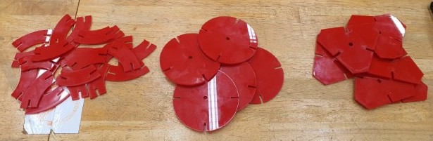
When ask to make a construction kit, the very first idea that came into my mind was those dinosaurs' forsils. But life, as usual, won't go easy for you. I need to design a construction kit with parametric factor and can do in multiple ways. So here are my designs:
Designing using FUSION360 software
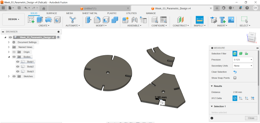
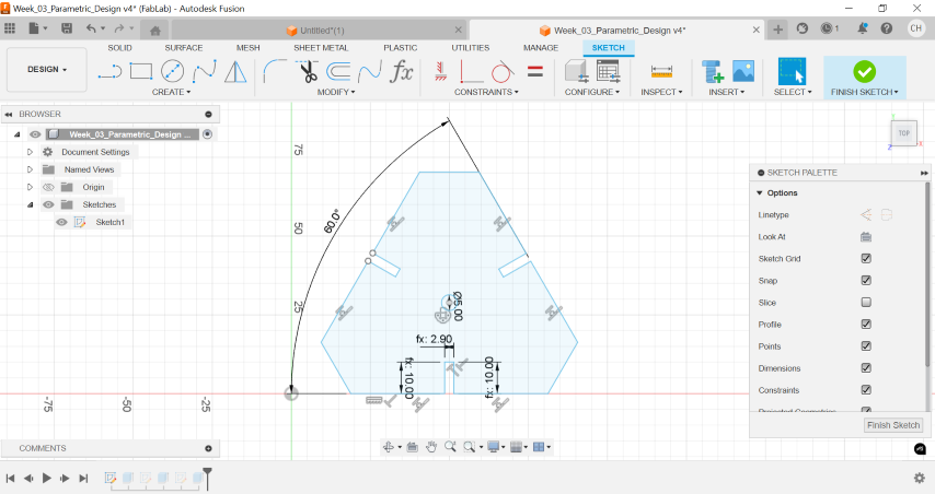
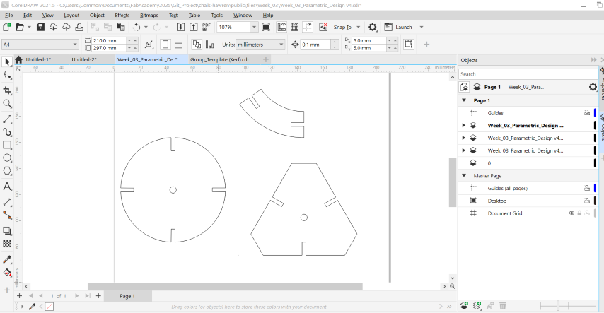
As shown, I have designed 2 different shapes of the flat pieces, along with a curved-design link bar. I have set 2 parameters, namely "t", which refers to thickness of the material that I used, and "SlotL", which refers to slot length.
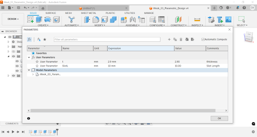 So whenever I wish to change any material with different thickness, I can just simply modify the figure in the "Change Parameter" tab, instead of editing seperate design. Same for the slot length. These 2 parameters will shown as an equation, e.g. fx. For my case, I will choose 10.00mm as my slot length value and 2.90mm as my thickness value after measured.
Line Setting and Alteration using CorelDRAW, Vector Cutting using Universal Laser Cutter
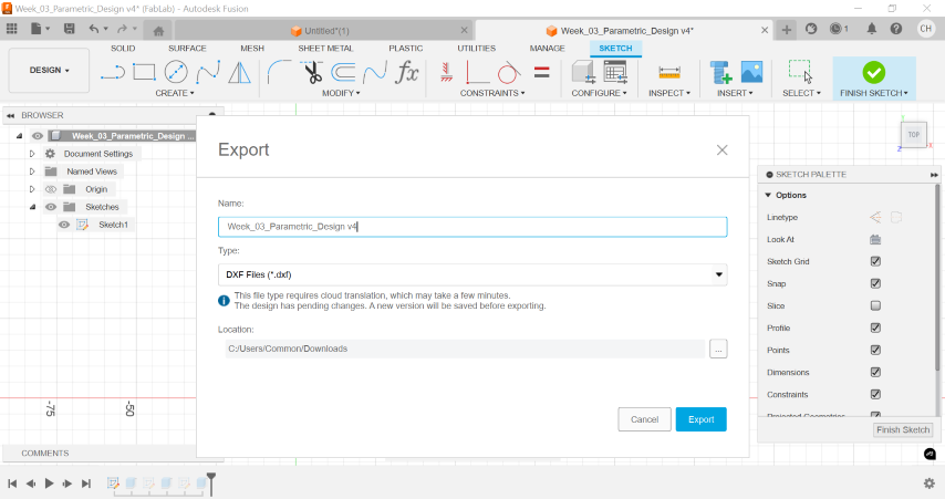
Before send for laser cutting, I will send my DXF file to CorelDRAW software, which allows me to program the line setting before send for laser cutting.
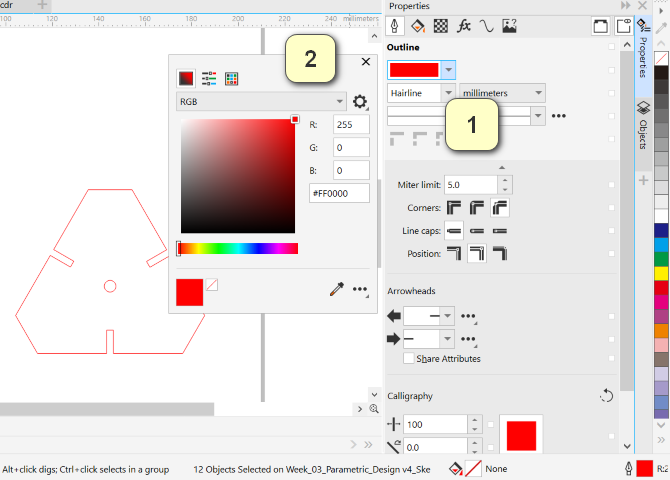
At first, I prepare the file by just set the line of 2 pieces of triangle piece to the setting below for vector cutting process:
1. Lightwweight = HAIRLINE.
2. Line colour = R255, G0, B0.
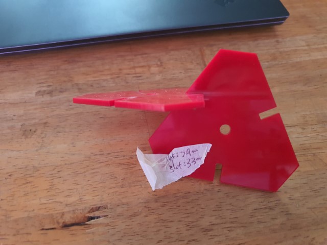
Turns out that the 2 pieces cannot press-fit and hold tight to each other when lifting up. After meassuring, the slots for both pieces become 3.30mm instead of the original meassured value (2.90mm). This means I need to "offset" the boundary by 2.0mm in order for me to create a press-fit slot.
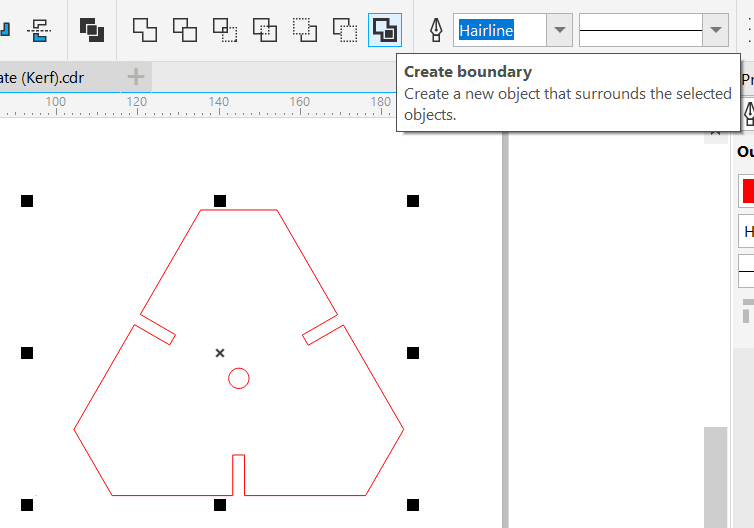
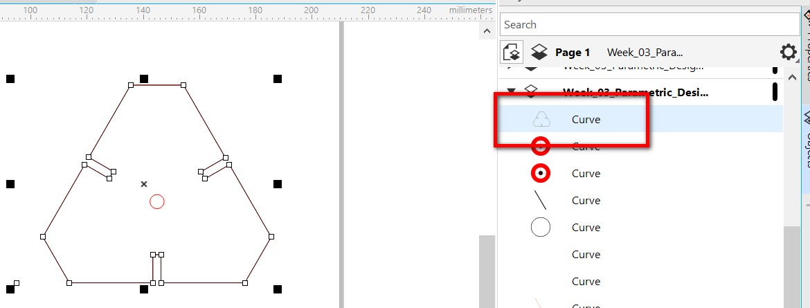
Return back to my CorelDRAW file, I need to recreate a new path that has a greater size of 2.0mm offset from the original path. Select the triangle piece, click "CREATE BOUNDARY", and you will see a new triangle piece with black line occurs. (refer to the OBJECT list.)
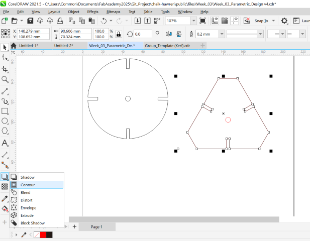
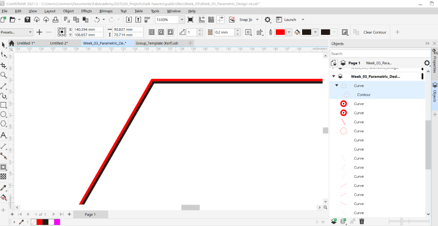
Select the "CONTOUR" button.Set the 1) Direction of the contour = Outside Contour, 2) Contour Offset = 0.20mm, 3) Change the Outline Colour = R255, G0, B0 (to differentiate between the path before modified and after modified). Break the contour line from the original curve, perform general setting before send for laser cutting process.
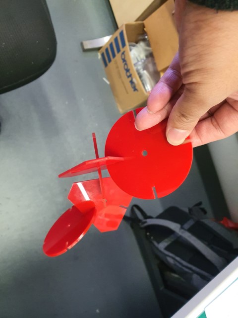
Ta-Da!! the slots for each piece hold well and tight and they never drop off even if I lift them up.
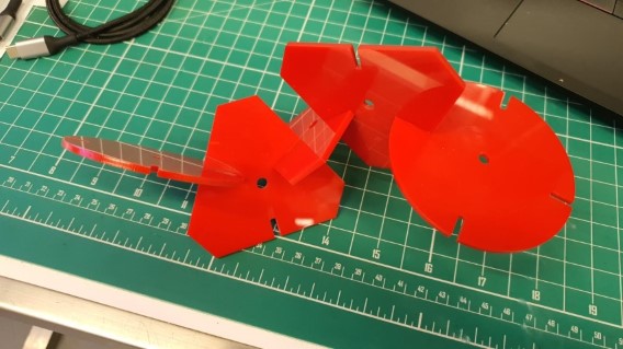
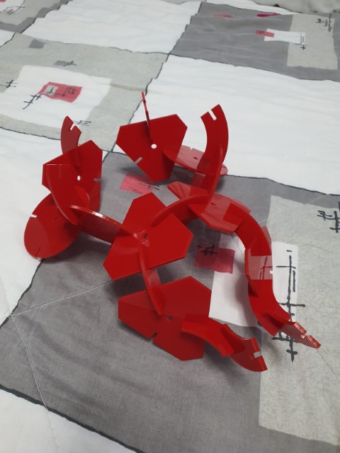
Once the details has confirmed, I proceed with another 2 patterns for variation. As the subsequent processes didn't take too long, I have made slightly more pieces for each design than what I planned.
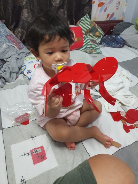
I brought the pieces back home and let my 2 little daughters try to build something with the kit, and these is what they thought off:

Reflection
After testing my parametric construction kit with my 2 daughters, 2 things have pointed out:
1. Need to choose an appropriate material that suitable for kids to enjoy themselves. Most of the time I am helping my kids to slot the pieces in because they don't have enough strength to push the pieces in due to tight press-fit.
2. Should have added chamfers at the corners of the slot for allowing pieces can be sloted in easier. Also, sharp edges and corners might harm users' skin.
Cut something on the vinyl cutter
Tracing an Image
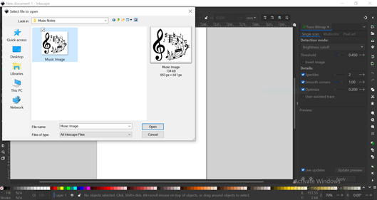
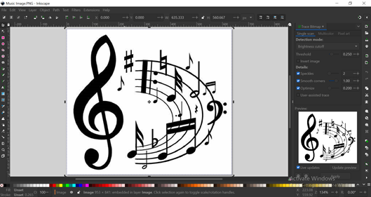
Since I am a music freak, I will choose a picture related to music.

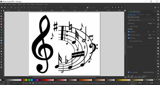
I choose Inkscape software to trace the outline of my image.
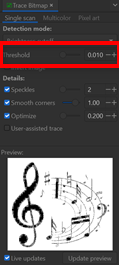
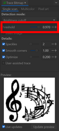
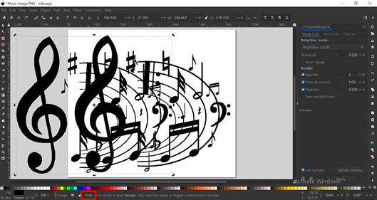
Select the entire image and click "Threshold" button - Adjust the “Threshold” option to optimal the visibility of the image. Smaller value will fade away the lines, while larger value will make the image looks darker. Click “Apply” button once confirm the “Threshold” value.
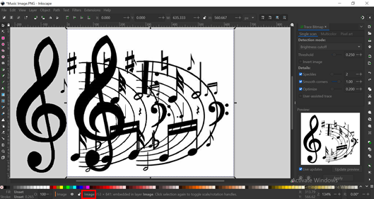
Remove the "IMAGE" file and save the "PATH" file as SVG file.
Vinyl Cutting
Open the saved SVG file using Silhouette Studio software and scale up the image file for better and clearer view for tracing.
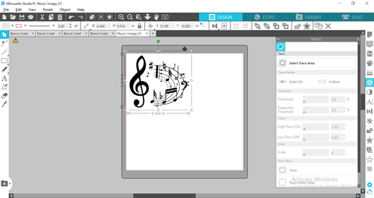
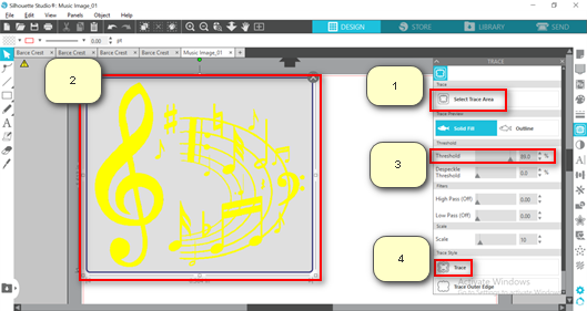
Select “Open the Trace Panel” on the right side panel and follow the steps below:
1) Click “Select Trace Area”.
2) Select the area.
3) Adjust the “Threshold” to make a better and clearer image.
4) Click “Trace” button.
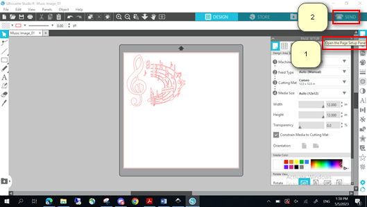
Remove the black image and remain the RED tracing image. Click “Open the Page Setup Panel” on the right side panel. Set the parameters in accordance to the correct vinyl cutter. For me I am choosing CAMEO vinyl Cutter. Click “SEND” button on the top right page.
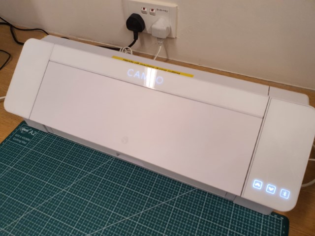
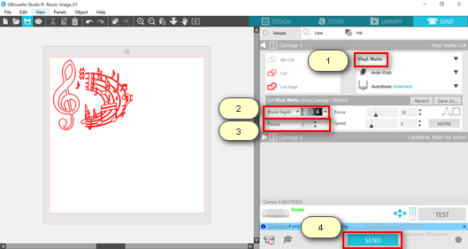
Connect to the correspondent vinyl cutter, set the appropriate parameters before click “SEND” button to start the cutting:
1) Sticker material.
2) the “Blade Depth”.
3) “Number of Passes”.
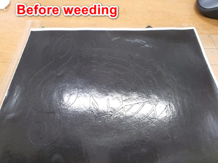
Ta-da!! It's done!! Below images show the sticker before and after weeding.

Reflection
Please ensure that the blade is sharp enough, or the settings are appropriate to avoid any moment struggling to weed out the unwanted parts. When the sticker never cut enough deep, you might be removing the entire piece rather than the small portion. Likeswise, if you cut too much, you might end up damage the sticker plate.